Weld Inspection and Soldering Microscopes
Feb 7th 2023
What to Look for when Purchasing a Welding or Soldering Microscope
Microscopes can be very useful when welding and soldering. There are several different things you may want to look for when purchasing a welding or soldering microscope.
Types of Welding Joints
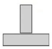
Different types of welding joints will have different strengths. It is important to be able to view the weld under the microscope to ensure that a strong weld is in place and the structure will not break when force is applied. Below are several of the common types of welding joints.
|
|
 |
 |
| Lap Joint | Tee Joint | Corner Joint |
 |
 |
|
| Butt Joint | Edge Joint |
What Magnification is Needed for Welding and Soldering?
Weld inspection is typically performed between 10x - 50x magnification. More details will be visible at higher magnification. Soldering work is typically performed at a lower magnification between 10x - 30x, allowing the user to clearly view more of the soldering sample.
What Type of Light is Best for Welding and Soldering?
Metals are highly reflective and therefore any type of soldering or welding work is best performed using a polarizing ring light. Each of the weld inspection microscopes include a LED polarizing ring light. This LED light has a built-in polarizer and a 360º rotatable analyzer to reduce glare and reflections. View images captured with a LED polarizing ring light here.
Weld Inspection Digital Microscope Options
There is incredibly powerful welding software available to make weld analysis easier than ever. This weld inspection digital microscope package includes software with customizable scripts so you can capture an image, run all necessary measurements, and export the data all with a single click. The image database software provides the ability to quickly and efficiently measure and document welding samples. Sample images and reports are archived in a searchable collection to document results over time.
The measurement feature provides quick measurement of welding cross-sections for fillet areas, throat, leg lengths, and penetration. Percent penetration is calculated for you automatically, and compared to your specs for a "PASS / FAIL" determination that displays on the screen. Using the software, a template can be placed over a live image for quick comparison and go/no go analysis of welds, prior to image capture.
Digital Weld Microscope Images
The weld images below were captured using a weld inspection microscope with PAX-it! software.
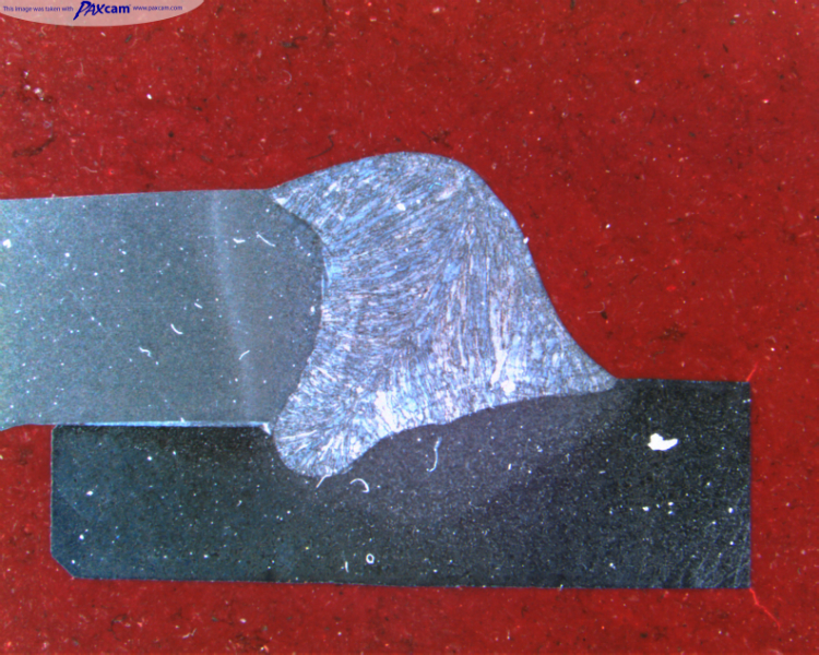
This is a weld cross section under a welding stereo microscope.
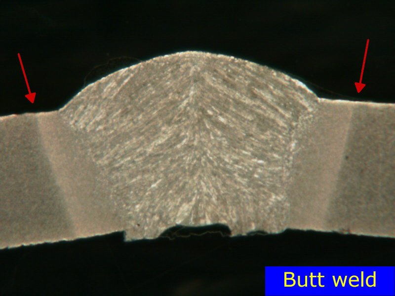
This is a butt weld, annotated using the PAX-it software.
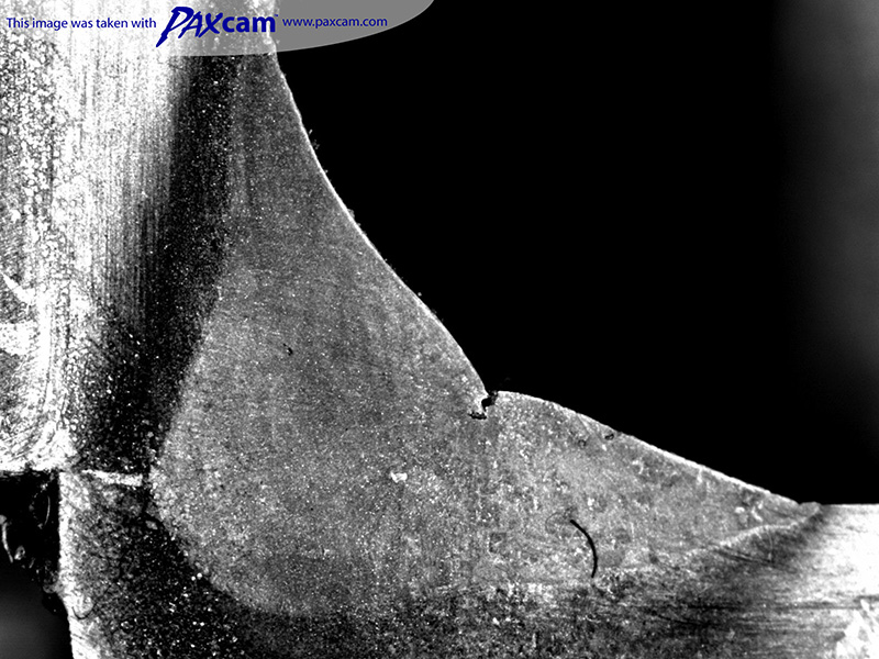
Weld section captured under the weld inspection microscope.
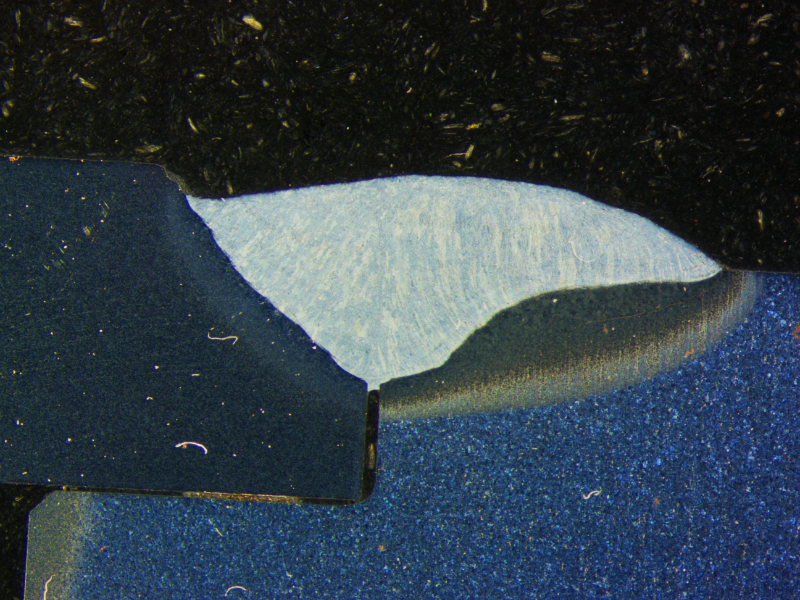
Weld cross section captured with HDR image processing in PAX-it software under the weld inspection microscope.
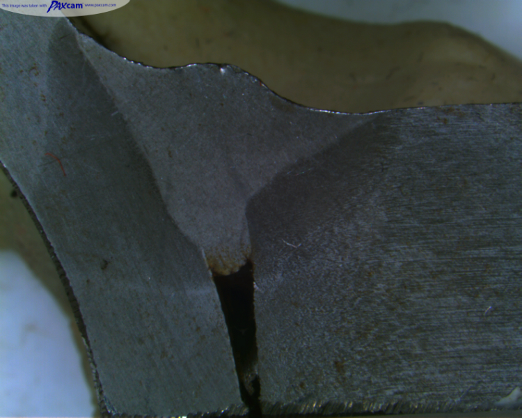
Weld cross section under the weld inspection microscope.
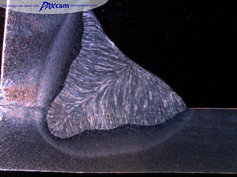
Weld section under the stereo microscope.
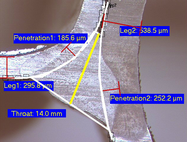
Tubing weld measured and annotated using the PAX-it software included with the digital weld microscope.
If you have any questions about weld inspection microscopes or soldering microscopes, please contact Microscope World for details.

